1. Introduction
In a related article about
distortion and globe effect in binoculars,
I have discussed the relationship between
pincushion distortion in binoculars and the globe
effect when the binocular is panning. With the present, somewhat
technical report, I want to take the opportunity to add a little
bit of mathematical background that is required to understand
the origin of the image curvature perceived through the panning
binocular.
2. Pincushion distortion in flat image space
The imaging equation of a binocular can be expressed as
 |
(1) |
were 'A' stands for the true angle of the object with respect to
the optical axis, 'a' for the apparent angle of its image with
respect to the center of field, and 'm' for the (paraxial)
magnification. The distortion 'k' defines the amount of
pincushion distortion of the resulting image space. The situation
is sketched in Fig. 1.
Figure 1:
A flat surface (wall) is imaged into the image space
of the binocular. During this process, the object angle 'A' is
transformed into the apparent angle 'a' through
Eq. (1).
Any radial distance to the center of field corresponds to the tangent
of that angle.
|
|
It is important to note that the special case k = 1 leads to
the so called tangent condition: The tangent of the true angle 'A'
is mapped into the tangent of the apparent angle 'a' through
a linear transformation (i.e. multiplication with the constant factor
'm'), delivering an image space that is free of distortion. Any other
value of 0 < k < 1 adds a corresponding amount of pincushion distortion
to the image. We may use Eq. (1) to solve for the
apparent angle:
![\begin{displaymath}
a = \frac{1}{k} \arctan\left[ m \cdot \tan \left( k\cdot A \right) \right]\;.
\end{displaymath}](img14.png) |
(2) |
Note that in our approach of Fig. 1 we
have assumed the mapping of a flat wall into a flat image space. Every radial
distance of the image point in this image space is then expressed as the
tangent of its apparent angle, leading to:
![\begin{displaymath}
\tan (a) = \tan \left\{ \frac{1}{k} \arctan\left[ m \cdot \tan \left( k\cdot A
\right) \right] \right\} \;.
\end{displaymath}](img15.png) |
(3) |
In the special case when 'k' equals unity, we
of course recover the tangent condition
 |
(4) |
and the image of a regular checkerboard pattern
is free of distortion (upper
left panel in Fig. 2).
Figure 2:
Checkerboards with various different amounts
of pincushion distortion, generated using Eq. (3).
The distortion parameter 'k' was defined in Eq. (1).
To generate these images, an undistorted
checkerboard pattern was imaged using telescopes with 10x power
and  true field of view.
|
|
3. Transformation into curved and undistorted space
Since the equation (3) generates a pincushion
distortion for every k < 1, if the image is projected onto a flat plane,
the question may arise whether or not it is possible to project
the image onto a curved surface instead, designed in such a way that
the observed distortion disappears. The motivation behind this idea is
that our brain tends to base its interpretation of images
on daily life experience. Among these experiences is the fact that
house-edges and lantern-poles do not bend when the view is
sweeping over the scenery. The pincushion distortion of binoculars
is causing such a bending of straight lines, and the brain tries
to re-interpret this visual experience through an image curvature:
The objects of the image remain rigid (= free of distortion), but
they are rolling over a curved surface.
Figure 3 displays
how this may look like: We are bending the image space such
that the radial (tape-measure) distance on the curved surface equals
the radial distance on the flat plane as it were in case of the tangent
condition, m tan(A). The resulting image would then follow the
tangent condition and be free of distortion - not on a plane
of course, but on a curved surface.
Figure 3:
We are looking for a curved image space with the
following property: The infinitesimal interval
tan(a+da) - tan(a) (green) which exhibits a pincushion distortion
on a flat surface is mapped onto a curved surface (red) such that the
corresponding interval
equals m d(tan A), i.e. it satisfies the tangent condition.
|
|
The math is straight forward and delivers curves as shown in
Fig. 4. The curved image space is parameterized
using a vector  , whose tip is generating the desired curve
while the apparent angle 'a' is sweeping over the field of view.
Since the imaging equation
is symmetric about the center of field, it suffices to analyse a
cross section of the image space that cuts through its center. For
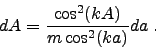
any infinitesimal increment of the angle 'a', the
tip of the vector has to satisfy the triangle condition
(compare with Fig. 3):
, whose tip is generating the desired curve
while the apparent angle 'a' is sweeping over the field of view.
Since the imaging equation
is symmetric about the center of field, it suffices to analyse a
cross section of the image space that cuts through its center. For
any infinitesimal increment of the angle 'a', the
tip of the vector has to satisfy the triangle condition
(compare with Fig. 3):
 |
(5) |
The differential delivers
 |
(6) |
and 'dA' is found through differentiation of Eq. 2,
yielding
 |
(7) |
Inserting that into the triangle condition Eq. 5 yields
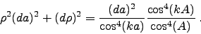 |
(8) |
Here we simplify the equation with the help of an approximation:
For binoculars, the true angle of view typically remains small,
so that the object angle 'A' (measured from the center of field)
rarely exceeds  . We can therefore assume
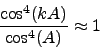 |
(9) |
throughout the field of view of the binocular. This yields the
differential equation for the magnitude of the vector  :
:
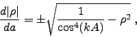 |
(10) |
of which we consider the positive branch only. Note that this equation coincides with another equation that describes
the curvature of the human visual space as defined in Ref. [1], with
the difference that the visual distortion parameter 'l' is
replaced with the instrumental distortion parameter 'k', and
the true angle 'A' with the apparent angle 'a'. The solutions
for these equations are therefore identical and plotted
in Fig. 4: For k = 1, the solution
 is found, which implies that the tip of the radius vector moves along
the x-axis and the image space is flat (Euclidean). This is no
surprise since we already know that in this case the tangent condition
delivers an undistorted image in flat image space. For k = 0, the
vector remains of
constant (unit-) length and its tip describes a circle - hence the
image space is spherical. Other parameter values in 0 < k < 1
deliver curvatures somewhere in between these two extremes,
Euclidean and spherical space.
is found, which implies that the tip of the radius vector moves along
the x-axis and the image space is flat (Euclidean). This is no
surprise since we already know that in this case the tangent condition
delivers an undistorted image in flat image space. For k = 0, the
vector remains of
constant (unit-) length and its tip describes a circle - hence the
image space is spherical. Other parameter values in 0 < k < 1
deliver curvatures somewhere in between these two extremes,
Euclidean and spherical space.
Figure 4:
Curvature of the image space as a function of the
distortion parameter 'k'. For k = 0, the space is
spherical, for k = 1 it is flat (Euclidean). The curves
are parameterized by the radius vector .
|
|
What we actually perceive through the ocular, however, is the
image that results from the superposition of both
the curvatures of image space (depending on 'k') and
of our visual space (depending on 'l').
If both curvatures coincide, k=l, then the resulting image
appears flat and the globe effect is perfectly eliminated.
In the case k > l, the image-space curvature is lower than
the visual space curvature and the globe effect is undercorrected.
In the opposite case, k < l, the globe effect is overcorrected,
i.e. the image appears to roll over a concave surface
(an "anti-globe" effect).
4. Summary
The pincushion distortion of a binocular or telescope can be
interpreted as an intrinsic image curvature. This is of relevance
because the human visual space can equivalently be shown as
being curved. The matching of both
image curvatures through the parameter choice k = l, with
'k' being the instrumental distortion and 'l' the visual distortion, is the
key to the elimination of the globe effect with the panning
binocular.
-
-
[1] H. Merlitz, Distortion of binoculars revisited: Does the
sweet spot exist?, J. Opt. Soc. Am. A 27, p. 50 (2010).
Here a PDF version of that paper.
Back Home
Last updated: April 2010
![\includegraphics[width=1.0\columnwidth]{wall_sketch_b.eps}](img12.png)
![\includegraphics[width=0.5\columnwidth]{helmholtz_a.eps}](img17.png)
![\includegraphics[width=0.5\columnwidth]{helmholtz_b.eps}](img18.png)
![\includegraphics[width=0.5\columnwidth]{helmholtz_c.eps}](img19.png)
![\includegraphics[width=0.5\columnwidth]{helmholtz_d.eps}](img20.png)
![\includegraphics[width=1.0\columnwidth]{metric.eps}](img23.png)
![\includegraphics[width=0.8\columnwidth]{curves_image.ps}](img38.png)